Sizing a decoupler tank is not as simple as sizing a chilled water buffer tank. Here we discuss why this is difficult, and the decisions that are often made because of it.
What is a decoupler?
Sometimes a buffer tank will be installed in a primary/secondary system. This buffer tank will have no baffle but requires 4 connection points.
In a primary/secondary system, the buffer tank would be installed in a manner to ensure both circuits are connected.
Chilled or heated water would be produced in the primary circuit, whereas chilled or heated water would be distributed around the building for air conditioning and space heating/cooling in the secondary circuit.
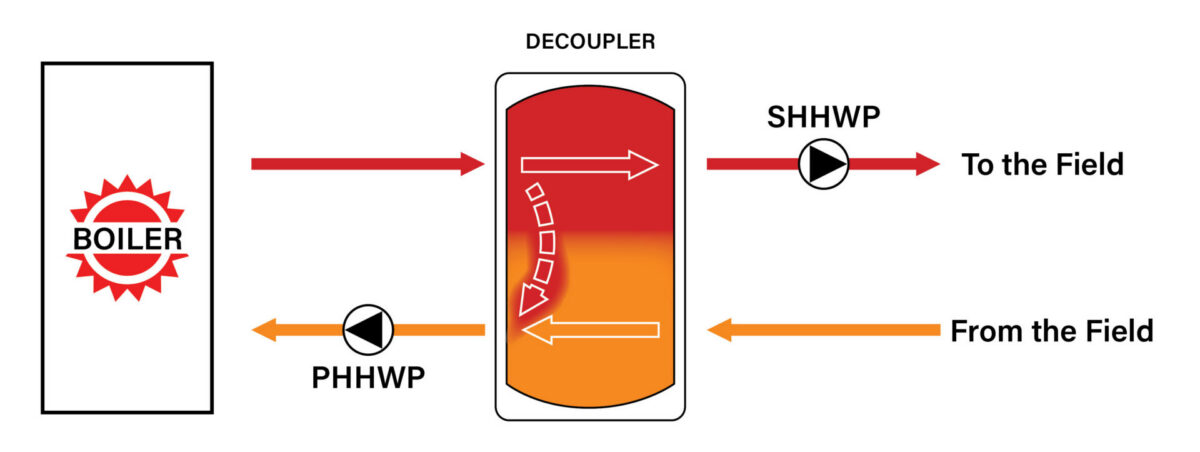
In a heating water circuit, the supply heating water will be on top and return cooler water will be on the bottom.
Heating Water System Decoupler Schematic Snapshot
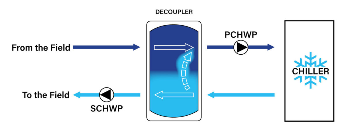
In a chilled water circuit, supply chilled water will be on the bottom and return warmer water will be on the top.
Chilled Water System Decoupler Schematic Snapshot
How does a decoupler work?
The water within the tank can flow either way, depending on the demand of the building.
In the rare instance that the building’s system is at maximum load and requires 100% of the system’s designed capacity, all the primary water will flow to the secondary circuit, which then disconnects/decouples both circuits from one another.
For the other 99% of the time, the system will be operating at part load.
In this scenario, some of the primary water will flow to the secondary circuit and some will pass through and head back to the chiller/boiler.
By effectively separating both system and chiller/boiler flow with minimum flow disturbances, a more constant delivery temperature (as well as a longer chiller/boiler operational cycle) can be achieved.
This reduces cycling, increases efficiency, and reduces the maintenance costs of the chiller/boiler.
Sizing a Decoupler Tank
Determining the correct size of a decoupler tank is more complex than with a simple buffer tank or storage tank. At Masterflow, we don’t believe there is any rule of thumb for this calculation.
We’ve noticed engineers sometimes attempt to incorporate the buffer and decoupling functions into one vessel. The more traditional approach is to design the system with the buffer tank and the decoupler as two separate items.
Sizing a standalone decoupler is based on flow rate. The size of a buffer tank is based on volume. You don’t necessarily need a buffer tank to decouple a system – this can be done with a smaller device such as a Hydraulic Separator or a low-loss header. In essence, a decoupler is a prefabricated low loss header.
Decoupler Function Alone
The function of a decoupler is solely to decouple, with no thermal storage or other influence. It is simply to accommodate for the difference in flow rates between the primary and secondary loops. This means a decoupler doesn’t normally have to be very large, with no greater than 150mm connections in most cases. We can supply Hydraulic Separators with connections up to 300mm.
Decoupler + Buffer Tank Functions Together
If a designer needs to add volume in a primary/secondary system and he decides to do this with a combined tank, we believe it will be hard to determine exactly how large the tank needs to be.
For example, a system requires 2000L of extra volume. You would install a buffer tank with 2000L of volume. However, when it is functioning as a decoupler, the effective volume would be less than 2000L due to the varying flow conditions within the tank (which is arranged as a decoupler – 4 connections, no baffle or sparge pipe). That is, the useable volume inside the tank cannot be accurately determined.
Because the effective volume is reduced due to the varying flow path, we have noticed designers have attempted to overcome this by substantially increasing the tank volume and increasing the height-to-diameter ratio. In the above example, the tank installed was 4500L, with a greatly increased height. In our opinion, a small Hydraulic separator could have been used. The overall cost would have been lower, due to a 2000L tank being sufficient.
Results
We prefer the separate approach because when you combine the two functions, the tank is always oversized. This wastes space, costs you more, and causes your system to lose efficiency. This is because it’s impossible to be certain if the full volume of the tank is being utilised. Because the purpose of a buffer tank is to add loop volume to the circuit, you always want to make sure you know exactly how much you are adding to the system.
When you include the decoupler and buffer tank as separate items, each can do their job better and you won’t have to spend extra on oversizing your tank.
Unsure whether your system needs a decoupler, buffer tank, or hydraulic separator? Speak with the Masterflow team for practical advice and correctly sized solutions for your application.
3min readBuffer tanks (also known as hydraulic separators) are used in hydronic heating systems to improve system performance and stability. While often associated with increasing system…
3min readOver the past 20years, we’ve seen and developed some interesting yet hazardous buffer tanks for areas such as mining precincts, nuclear energy plants and even…
2min readChallenge A client reached out to us with questions about the pressure reading of their expansion tanks, as they were not operating within the expected…