Buffer tanks (also known as hydraulic separators) are used in hydronic heating systems to improve system performance and stability. While often associated with increasing system volume, their function is more specific. Managing heat energy, reducing boiler cycling, and separating system flow from boiler flow.
This article explains how buffer tanks: • Reduce boiler cycling • Store thermal energy (BTUs) • Are sized using runtime calculations • Operate internally under different flow conditions
Boiler Cycling and Why It Matters
Boiler cycling refers to the repeated starting and stopping of a boiler.
This occurs when the minimum system load is less than the minimum output of the boiler. In this condition, the boiler delivers more BTUs than the system requires, causing it to shut off and restart repeatedly.
Excessive cycling can result in: • Erratic system delivery temperatures • Premature component failure • Reduced boiler efficiency
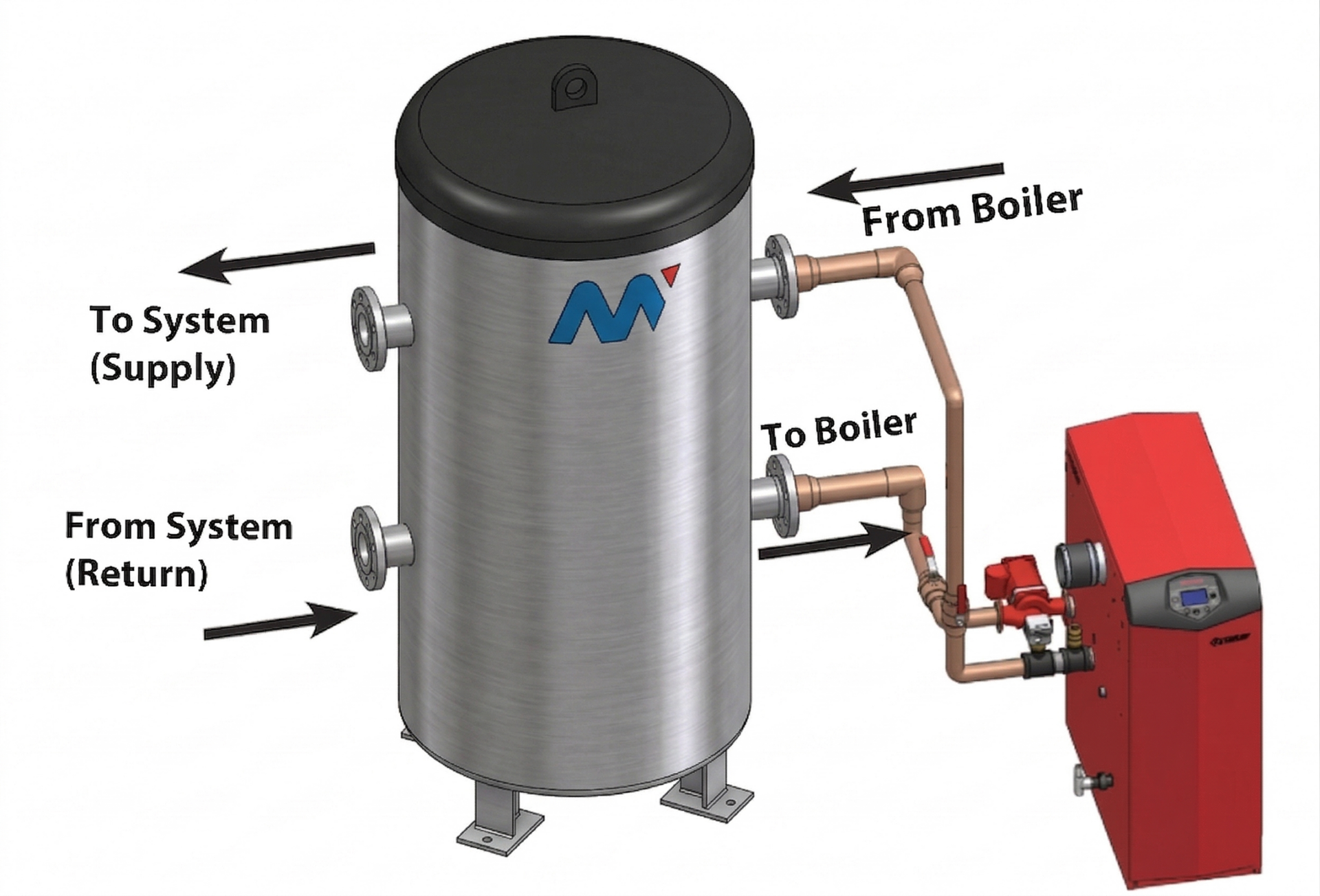
Typical Piping Arrangement for Buffer Tank/Hydraulic Separator in Hydronic Systems
How Buffer Tanks Store BTUs
A buffer tank is designed to act as a “battery for BTUs.”
When the boiler produces more heat than the system requires, the excess energy is stored in the tank water. The system demand is then met using the BTUs already stored in the tank, delaying the need for the boiler to initiate another heating cycle.
This allows the boiler to operate for longer periods and helps achieve a minimum runtime.
The Runtime Formula (Sizing the Tank)
A buffer tank is sized to provide a minimum runtime for the boiler plant.
Buffer Tank Capacity =Desired Runtime × (Minimum Boiler Output − Minimum System Load) System ΔT × 8.33 × 60 (8.33 lb/gal ≈ 1 kg/L, 60 min/hr)
Where:
Desired Runtime = minimum period the boiler should run before cycling off
Minimum Boiler Output = lowest firing rate of the smallest boiler
Minimum System Load = smallest heating demand of the building
System ΔT = difference between system supply and return temperature
8.33(8.33 lb/gal ≈ 1 kg/L) = weight of one gallon of water
60 = minutes in one hour
Lochinvar recommends a minimum boiler runtime of no less than 10 minutes.
What Happens Inside a Buffer Tank / Hydraulic Separator
A buffer tank also functions as a hydraulic separator, de-coupling the boiler flow from the system flow so that the two independent flows do not affect one another.
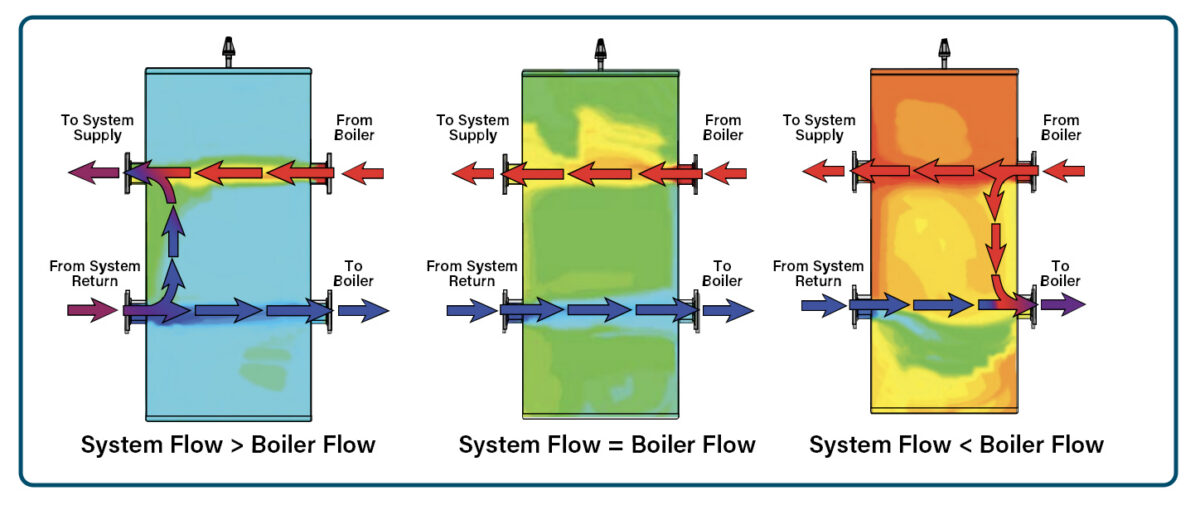
Depending on the relationship between system flow and boiler flow, the tank behaves differently:
1. System Flow Greater Than Boiler Flow • The system flow exceeds the boiler flow • Additional flow is supplied from the tank • Mixing occurs within the tank
2. System Flow Equal to Boiler Flow • System flow and boiler flow are balanced • Flow passes directly through the tank • Minimal mixing occurs
3. System Flow Less Than Boiler Flow • Boiler flow exceeds system flow • Excess flow enters the tank • Thermal energy is stored within the tank • These conditions allow the system to maintain stable operation under varying load requirements.
Summary
Buffer tanks are used to:
reduce boiler cycling
store excess thermal energy (BTUs)
ensure minimum boiler runtime through proper sizing
separate boiler flow from system flow
These functions improve system stability, efficiency, and overall performance in hydronic heating systems.
3min readOver the past 20years, we’ve seen and developed some interesting yet hazardous buffer tanks for areas such as mining precincts, nuclear energy plants and even…
2min readChallenge A client reached out to us with questions about the pressure reading of their expansion tanks, as they were not operating within the expected…
2min readCorrosion Is Nobody’s Friend While your buffer tank’s stainless steel and mild steel bodies are highly corrosion resistant, they are designed with a very mild…