A fouling factor is a design allowance added to a heat exchanger’s required surface area to compensate for thermal resistance caused by deposit build-up over time.
Unlike Shell & Tube Heat Exchangers, Plate Heat Exchangers (PHEs) are generally designed without applying excessive fouling margins. This isn’t an oversight, it it is primarily due to the operating characteristics of plate heat exchangers.
PHEs have inherent characteristics that significantly reduce the tendency for fouling in the first place:
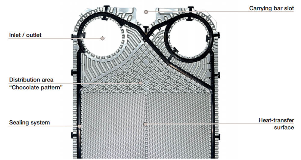
• Highly turbulent flow: PHEs maintain highly turbulent flow, even at relatively low fluid velocities. This turbulence significantly reduces the tendency for fouling or scaling to accumulate on the heat transfer surfaces.
• Self-cleaning corrugated plate design: The corrugated plate design promotes continuous self-cleaning by generating high wall shear stresses, minimising deposit build-up compared to conventional heat exchangers.
• Low fouling tendency in closed-loop systems: In closed-loop systems with treated water quality, the fouling tendency is already very low, making additional fouling allowances generally unnecessary.
• Easy to maintain: In the unlikely event of fouling, the unit can be easily opened, inspected, and cleaned, fully restoring the original thermal performance.
Why Oversizing a Plate Heat Exchanger Increases Fouling Risk
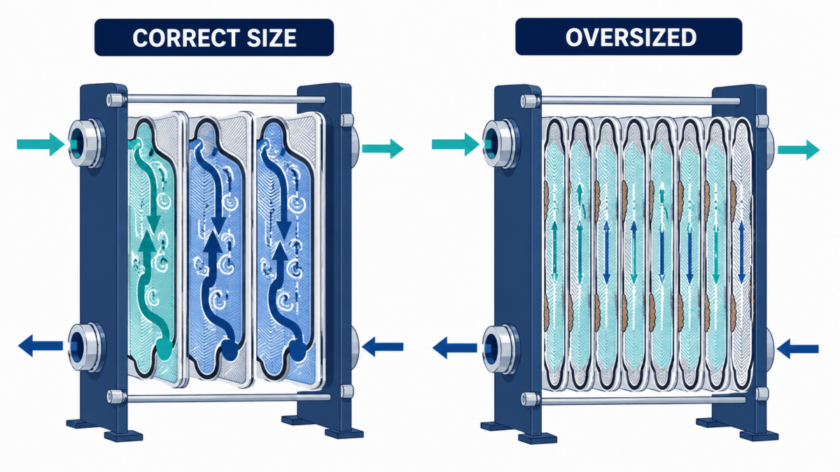
Applying a high fouling factor in the design stage typically results in oversizing the PHE, leading to unnecessary additional plates, higher pressure drops, increased footprint, and added project cost, all without providing any practical operational benefit.
Worse, oversizing can actually accelerate fouling. Traditional fouling factors artificially increase the required surface area, often by 30% or more. This larger surface area reduces the fluid’s cross-channel velocity and turbulence, lowering wall shear stress and making deposits more likely to form, not less.
In a heat exchanger, shear stress (often referred to as wall shear stress) is the frictional force that a flowing fluid exerts tangentially along the inner surfaces of pipes or plates. It measures the fluid’s dragging force per unit area on the metal, driving heat transfer and preventing particulate buildup.
How Fouling Is Managed in Plate Heat Exchanger Design
Rather than applying an arbitrary fouling factor (such as 0.0005 m²·K/W), the approach relies on maintaining high fluid turbulence to create “SelfClean” conditions, with an over surface margin applied to handle natural process variations, without compromising flow velocity.
This is achieved through three methods:
Wall Shear Stress Analysis: Fluid velocity and plate corrugation are matched to ensure shear stress is high enough to prevent deposits from adhering to the plates.
Cleanliness / Safety Margins: Design margins ensure that even if a slight film or deposit builds up over time, overall thermal performance remains within process requirements.
Corrugation and Channel Selection: Different chevron angles (hard vs. soft plates) and plate pressing depths are selected based on fluid properties, including viscosity and suspended solids.
Need help sizing a heat exchanger for your project?
Because PHE fouling is highly dependent on specific process variables, fluids, and operating temperatures, arbitrary defaults should not be used. Contact the Masterflow team to have our engineers calculate the right solution for your application.
FAQ
A fouling factor is a design allowance added to a heat exchanger’s required surface area to compensate for the thermal resistance caused by deposit build-up over time. It is commonly used in Shell & Tube heat exchanger design to account for scaling, sediment, and other deposits that reduce heat transfer performance.
Generally, no. Plate heat exchangers are designed with highly turbulent flow and corrugated plates that promote a self-cleaning effect, significantly reducing the tendency for fouling to accumulate. In closed-loop systems with treated water, the fouling tendency is already very low, making additional fouling allowances unnecessary in most applications.
Applying a large fouling factor increases the required surface area, which reduces the fluid’s cross-channel velocity and turbulence inside the exchanger. Lower turbulence means lower wall shear stress — the very condition that normally sweeps deposits away. This can actually encourage fouling rather than prevent it, making oversizing counterproductive.
Rather than applying an arbitrary fouling factor, Masterflow accounts for fouling through wall shear stress analysis, cleanliness and safety margins, and careful corrugation and channel selection. This ensures the exchanger maintains the turbulence and flow conditions needed to resist fouling naturally, without unnecessary oversizing.
4min readWhat is AHRI Certification? AHRI (Air Conditioning Heating & Refrigeration Institute) was founded in North America, with a rich origin story beginning in 1888. The…
5min readHeat exchangers are complex pieces of equipment. We’re going to start with basic science to help explain the purpose and process of the workings of…