Plate Heat Exchangers 101
Heat exchangers are complex pieces of equipment.
We’re going to start with basic science to help explain the purpose and process of the workings of a heat exchanger.
Breaking Down the Definition
The generic term “heat exchanger” refers to a system used to transfer heat between a source and a working fluid.
System
A heat exchanger is used as part of the refrigeration circuit.
This changes the pressure and state of the refrigerant between gas and liquid to allow the absorbing of heat from the air inside a building and the transfer of this heat to the air outside.
This would be the case in a system designed to cool a room down.
Transfer
Here thermodynamics is used to carry heat from one ‘object’ to another.
When a hot object is put in contact with a cold object, heat from the hot object is transferred to the cold object until both reach the same temperature.
However, once the objects are drawn apart, they do not return to their original temperatures.
Source
The ‘source’ in thermodynamics is a reservoir that supplies energy in the form of heat to be absorbed by a ‘sink’, which is the other ‘object’ involved in the heat transfer.
In an HVAC system, the source would be the water being pumped through pipework around the building.
Working fluid
A working fluid is a liquid or gas that primarily transfers motion, force, or mechanical energy.
The working fluid in an HVAC system is usually refrigerant or ‘coolant’. The working fluid of a system will be the ‘sink’ of the heat transfer.
Types of Heat Exchangers
Heat exchangers come in many different forms, each under a category of:
- Air-to-Air (like Airchange)
- Water-to-Air (water coil to AHU (Air Handling Units))
- Water-to-Water
Water-to-water heat exchangers are the most popular kind for the HVAC industry. The most common forms of water-to-water heat exchangers include:
- Plate heat exchangers
- Shell and tube heat exchangers
We’ve given an honest review of the two in the article “Plate vs Shell + Tube Heat Exchangers”.
Masterflow distributes Alfa Laval’s Gasketed and Brazed Plate Heat Exchangers.
Applications in HVAC Systems
Space Heating & Cooling
PHEs play a pivotal role in space heating and cooling, transferring heat between HVAC systems and air to regulate indoor temperatures effectively.
Domestic Hot Water Systems
In residential and commercial settings, PHEs efficiently transfer heat from primary sources, such as boilers, to water supplies.
Refrigeration Systems
Applied in refrigeration systems, PHEs facilitate heat exchange between refrigerants and other fluids, crucial for maintaining optimal temperatures.
How do Plate Heat Exchangers Work?
A plate heat exchanger implements these functions by directing the system water through channels created by thin, corrugated metal plates.
These plates are stacked together in a ‘plate pack’, where each pair of plates form a channel for the fluid to flow through.
The source fluid and the sink fluid will flow past each other in a counter-current, never making contact. The metal plates will allow the transfer of heat from one to the other.
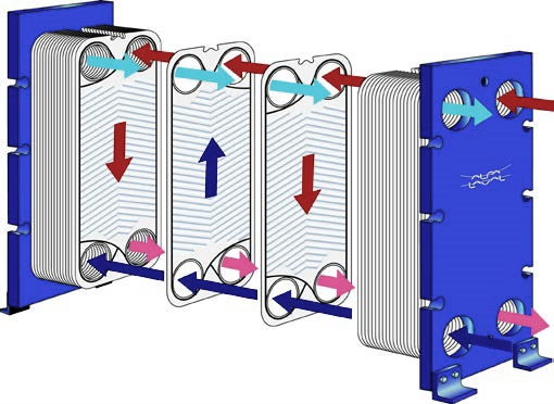
The below diagram illustrates how a gasketed plate heat exchanger works.
Diagram A:

Heating Water Systems
The room-temperature fluid (the sink) flows into the heat exchanger at the base, entering the channels where it finds an opening.
The hot fluid (the source) enters the heat exchanger at the top and on the opposite side to the room-temperature fluid.
Its open channels alternate with the room-temperature liquid’s open channels to ensure the fluids do not make contact.
When the liquids exit the heat exchanger, they will be similar in temperature.
This means the source fluid can return through the refrigeration circuit and be heated again, while the sink fluid (having now absorbed heat from the source) can be pumped around the building to supply heating.
Chilled Water Systems
In the case of supplying cool air rather than heating, the heat exchanger will see cold fluid flow through as the source, while room-temperature fluid (the sink) loses heat to the cold fluid and therefore becomes colder.
This can then be pumped around the building to supply air conditioning.
Plate Heat Exchanger Componentry
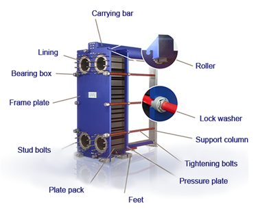
Each plate heat exchanger should come equipped with the following components (see diagram below):
- Carrying Bar
- Frame Plate
- Lock Washer
- Support Column
- Stud Bolts
- Tightening Bolts aka “Tie Bolts”
- Pressure Plate
- Plate Pack
- Swing Feet
- Lining not applicable for unlined units
- Roller larger units only
- Bearing Box larger units only
Please ensure all these components (where applicable) are included in the heat exchanger quotes you receive. We’ve created this handy downloadable checklist for your benefit.
Diagram B:

Heat Exchanger Plates
You’ll need X number of flow channels of a certain plate design to a) meet the heat transfer requirements and b) stay within specified pressure drop (resistance) requirements.
Heat exchanger plate designs include, but are not limited to:
- Washboard
- Chevron/herringbone
- Zigzag
- Protrusions and depressions
Plate Heat Exchanger Calculations
The most important parameters you need to know for Plate Heat Exchanger calculations are:
- Inlet and outlets temperatures on the primary and secondary sides
- Maximum allowable pressure drop on the primary and secondary sides
- Flowrates on the primary and secondary sides
- Maximum operating temperature
- Maximum operating pressure
- Amount of heat to be transferred (heat load)
The heat load can be calculated if the flow rate, specific heat and temperature difference are known for one side of the heat exchanger.
To calculate the heat load:

P = Heat load (btu/h)
m = Mass flow rate (lb/h)
cp = Specific heat (btu/lb °F)
δt = Temperature difference between inlet and outlet on one side (°F)
k = Heat transfer coefficient (btu/ft2 h °F)
A = Heat transfer area (ft2)
LMTD = Log mean temperature difference
To calculate Theta:

T1 = Inlet temperature – hot side
T2 = Outlet temperature – hot side
T3 = Inlet temperature – cold side
T4 = Outlet temperature – cold side
To calculate LMTD (Log Mean Temperature Difference):

Where the change in T1 = T1-T4, and the change in T2 = T2-T3.
To calculate the heat transfer coefficient and design margin:

α1 = Heat transfer coefficient between the warm medium and the heat transfer surface (btu/ft2 h °F)
α2 = Heat transfer coefficient between the heat transfer surface and the cold medium (btu/ft2 h °F)
δ = Thickness of the heat transfer surface (ft)
Rf = Fouling factor (ft2 h °F/btu)
λ = Thermal conductivity of the material separating the medias (btu/ft h °F)
kc = Clean heat transfer coefficient (Rf=0) (btu/ft2 h °F)
k = Design heat transfer coefficient (btu/ft2 h °F)
M = Design Margin (%)
Combination of these two formulas gives: M = kc · Rf
Alfa Laval goes further into the theory of heat transfer in their brochure.
